P&ID Symbols and Notation
P&ID Symbols and Notation
As we all know that the industrial P&ID diagram comprised of specific symobols (P&ID Symbols) having specific shape special notation .
In this article we will see different symbol and notations used to create a P&ID diagram as per industrial process . A huge variety of symbols is used to craete a standard P&ID diagram.
Here in this article we will go through these topic of contents which will give you a good idea regarding P&ID creation.
Topic of Contents
About P&ID symbols
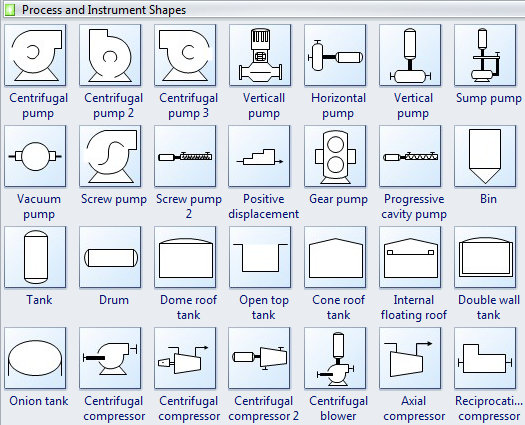
Piping and Instrumentation Diagram Standard Symbols Detailed Documentation provides a standard set of shapes & symbols for documenting P&ID and PFD, including standard shapes for instrument, valves, pump, heating exchanges, mixers, crushers, vessels, compressors, filters, motors and connecting shapes.
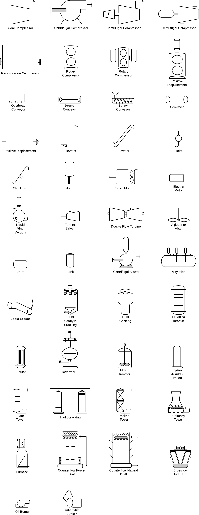
Equipment symbols
An equipment is comprised of miscellaneous P&ID units that don’t fit into the other categories. This group includes various individual components like compressors, conveyors, motors, pumps, turbines, pneumatic controllers, vacuums, and other mechanical devices.
Piping symbols
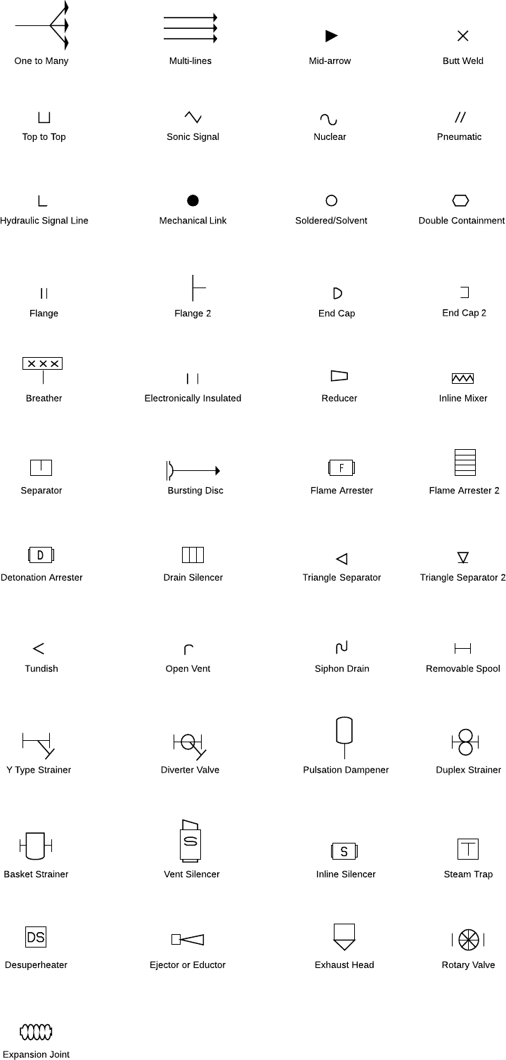
Various symbols are used to indicate piping components, instrumentation, equipments in engineering drawings such as Piping and Instrumentation Diagram (P&ID), Isometric Drawings, Plot Plan, Equipment Layout, Welding drawings etc. Checkout list of such symbols given below.
Piping can be made of various materials, including metal and plastic. The piping group is made up of one-to-many pipes, multi-line pipes, separators, and other types of piping devices.
Vessel symbols

Heat exchanger symbols

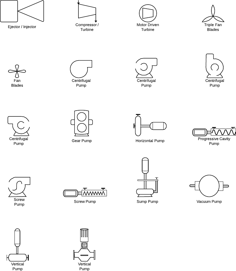
Pump symbols
Valve Symbols

Static Equipment and Distillation column


Line Symbols for PFD and P&ID

SourceArticle : Lucidchart
Read Also :
Piping and Instrumentation Diagram – P&ID
Process Flow Diagram (PFD)
Piping Systems Codes and Standards
Also Read Another Content:
What is Boiler ?
Venturi Flow Meter
Pitot Tube
Coriolis Mass Flow Meter









Very much useful these all