A thermocouple is comprised of at least two metals joined together to form two junctions. One is connected to the body whose temperature is to be measured; this is the hot or measuring junction. The other junction is connected to a body of known temperature; this is the cold or reference junction. Therefore the thermocouple measures unknown temperature of the body with reference to the known temperature of the other body.
Reference
Book: Mechanical Measurements by Thomas G. Beckwith and N. Lewis Buck
Principle of Working of Thermocouple
1) Seebeck effect: The Seebeck effect states that when two different or unlike metals are joined together at two junctions, an electromotive force (emf) is generated at the two junctions. The amount of emf generated is different for different combinations of the metals.
3) Thomson effect: As per the Thomson effect, when two unlike metals are joined together forming two junctions, the potential exists within the circuit due to temperature gradient along the entire length of the conductors within the circuit.
Diagrams
How it Works
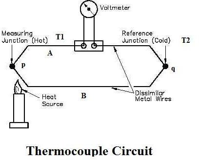
The general circuit for the working of thermocouple is shown in the figure 1 above. It comprises of two dissimilar metals, A and B. These are joined together to form two junctions, p and q, which are maintained at the temperatures T1 and T2respectively. Remember that the thermocouple cannot be formed if there are not two junctions. Since the two junctions are maintained at different temperatures the Peltier emf is generated within the circuit and it is the function of the temperatures of two junctions.
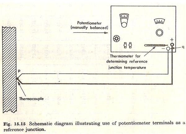
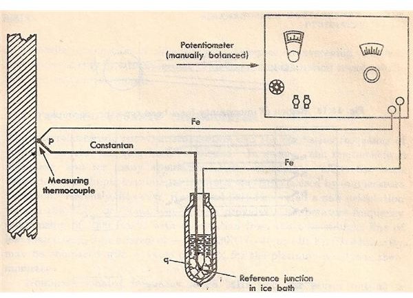
The device for measuring the current or emf is connected within the circuit of the thermocouple. It measures the amount of emf flowing through the circuit due to the two junctions of the two dissimilar metals maintained at different temperatures. In figure 2 the two junctions of the thermocouple and the device used for measurement of emf (potentiometer) are shown.
Now, the temperature of the reference junctions is already known, while the temperature of measuring junction is unknown. The output obtained from the thermocouple circuit is calibrated directly against the unknown temperature. Thus the voltage or current output obtained from thermocouple circuit gives the value of unknown temperature directly.
Types of Thermocouples:
Before discussing the various types of thermocouples, it should be noted that a thermocouple is often enclosed in a protective sheath to isolate it from the local atmosphere. This protective sheath drastically reduces the effects of corrosion.
Temperature Range:
Accuracy (whichever is greater):
- Standard: +/- 2.2C or +/- .75%
- Special Limits of Error: +/- 1.1C or 0.4%

Temperature Range:
Accuracy (whichever is greater):
- Standard: +/- 2.2C or +/- .75%
- Special Limits of Error: +/- 1.1C or 0.4%

Temperature Range:
Accuracy (whichever is greater):
- Standard: +/- 1.0C or +/- .75%
- Special Limits of Error: +/- 0.5C or 0.4%

Temperature Range:
Accuracy (whichever is greater):
- Standard: +/- 1.7C or +/- 0.5%
- Special Limits of Error: +/- 1.0C or 0.4%

Temperature Range:
Accuracy (whichever is greater):
- Standard: +/- 2.2C or +/- .75%
- Special Limits of Error: +/- 1.1C or 0.4%
NOBLE METAL THERMOCOUPLES (Type S,R, & B):
Noble Metal Thermocouples are selected for their ability to withstand extremely high temperatures while maintaining their accuracy and lifespan. They are considerably more expensive than Base Metal Thermocouples.

Temperature Range:
Accuracy (whichever is greater):
- Standard: +/- 1.5C or +/- .25%
- Special Limits of Error: +/- 0.6C or 0.1%

Temperature Range:
Accuracy (whichever is greater):
- Standard: +/- 1.5C or +/- .25%
- Special Limits of Error: +/- 0.6C or 0.1%
Temperature Range:
Accuracy (whichever is greater):
- Standard: +/- 0.5%
- Special Limits of Error: +/- 0.25%
Devices Used for Measuring EMF
The amount of emf developed within the thermocouple circuit is very small, usually in millivolts, therefore highly sensitive instruments should be used for measuring the emf generated in the thermocouple circuit. Two devices used commonly are the ordinary galvanometer and voltage balancing potentiometer. Of those two, a manually or automatically balancing potentiometer is used most often.
Figure 2 shows the potentiometer connected in the thermocouple circuit. The junction p is connected to the body whose temperature is to be measured. The junction q is the reference junction, whose temperature can be measured by the thermometer. In some cases the reference junctions can also be maintained at the ice temperature by connecting it to the ice bath (see figure 3). This device can be calibrated in terms of the input temperature so that its scale can give the value directly in terms of temperature.
Thermocouple vs. RTD
Temperature range:
First, consider the difference in temperature ranges. Noble Metal Thermocouples can reach 3,100 F, while standard RTDs have a limit of 600 F and extended range RTDs have a limit of 1,100 F.
Cost:
A plain stem thermocouple is 2 to 3 times less expensive than a plain stem RTD. A thermocouple head assembly is roughly 50% less expensive than an equivalent RTD head assembly.
Accuracy, Linearity, & Stability:
As a general rule, RTDs are more accurate than thermocouples. This is especially true at lower temperature ranges. RTDs are also more stable and have better linearity than thermocouples. If accuracy, linearity, and stability are your primary concerns and your application is within an RTD’s temperature limits, go with the RTD.
Durability:
In the sensors industry, RTDs are widely regarded as a less durable sensor when compared to thermocouples. However, REOTEMP has developed manufacturing techniques that have greatly improved the durability of our RTD sensors. These techniques make REOTEMP’s RTDs nearly equivalent to thermocouples in terms of durability.
Response Time:
RTDs cannot be grounded. For this reason, they have a slower response time than grounded thermocouples. Also, thermocouples can be placed inside a smaller diameter sheath than RTDs. A smaller sheath diameter will increase response time. For example, a grounded thermocouple inside a 1/16” dia. sheath will have a faster response time than a RTD inside a ¼” dia. sheath.
ArticleSource : Bright Hub Engineering ; Thermocoupleinfo
Images Courtesy
1) Book: Mechanical Measurements by Thomas G. Beckwith and N. Lewis Buck
2) https://www.tpub.com/content/doe/h1013v1/css/h1013v1_24.htm


